How to design your software using UML diagrams [with case study]
Coding (Php 7.x)
Write proper code and avoid error by using UML diagrams, a standard that will let you design you application properly from the ground-up
What is Unified Modeling Language?
The 3rd August 1492 Cristoforo Colombo in charge of three ships called the Niña, the Pinta and the Santa Maria set sail for one of the most incredible discoveries of all times.
We all know the details about him and his trips but we know less about those ships and how they were made.
You see, even at that time, to make a ship, naval engineers needed to study and incorporate elements of mechanical, physical and safety engineering using various blueprint and diagrams.
In software development, if we want to build reliable and durable applications, we have to do the same, and we do so by using Unified Modeling Language.
UML is an industry-standard graphical language that helps developers specify, visualize, construct and document the characteristics of a software system.
It uses graphical notes to design object-oriented analysis of programs and applications.
Why web developers use UML?
Let’s start by saying that UML can be used by anybody that needs to create a system, any sort of system either regarding software engineering or not.
In specific, web developers use UML before creating an application so that can have a clear path and all the implementations that needed to be featured in mind,
As a naval engineer need to know all the characteristics of a ship he needs to build, we can create the best system possible after having analyzed the requirement of the project we are working on.
The reason we use UML is to have a clear structure, a blueprint of the application beforehand,
Analyzing and designing all possible advantages and issues that can show up during the development process before we start writing the code has an enormous cost and time advantage.
The class diagrams
There are several types of diagrams included in UML but the most used, because of its utility when designing OOP relationship is, without doubt, the class diagram,
The class diagram is a visual representation of all the classes and relationship you might need to use in your project.
If you already came across a software design pattern representation you have already seen a class diagram, all the relationship between classes, methods and attributes are described using this type of Unified Modeling Language.
This UML has a few standards that you need to follow when creating the diagram but they are all basic and easy to understand.
You can see more in the official website
There are several free online tools that you can use to create class diagram UML, I prefer pen and paper but for this post, I am going to link some of the best tools here:
In this tutorial, I am going to create UML scheme for Columbus Travels, a luxury cruise line for new exciting discoveries.
How to represent class using UML?
Let’s start with a disclosure, I am not near to be an expert of cruises so the UML examples here can be very far from an actual application that requires weeks if not months of discovery,
Said that let’s move on.
It is surely clear that a class diagram has as fundamental element: the classes, and here is where we start.
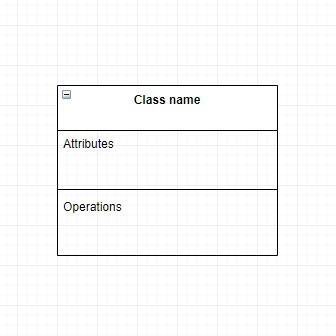
The UML structure of a class is represented by a box.
It is divided into 3 horizontal sections.
In the top one, there is the name of the class, in our case the class I choose to start with is the class cruise.
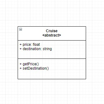
Now, a customer can choose to get on board of different types of cruises, let’s say we got American, Mediterranean, and for whom who prefer cool avenues, we offer Arctic cruises as well.
This to me screams abstract class, Using UML we have two different ways to describe abstractions, writing the name of the class in italic or using the syntax below.
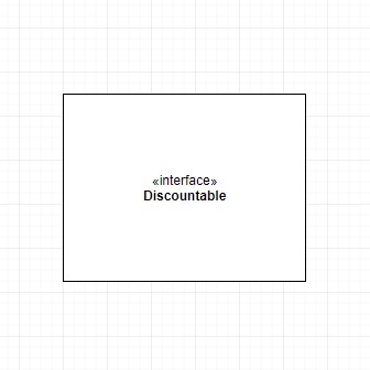
Interfaces instead are represented with the following syntax.
Writing attributes
Surely you know that a class includes attributes and methods, and these two features are going to fill the other two sections of the UML box.
If you need to brush up how an object is created in OOP have a look at the basics of PHP
The elements within a class can have one of three different types of visibility, they are public, private and protected.
In a class diagram, we represent them using the symbols + for the public, - for private and # for the protected one.
Attributes are going to be inserted inside the second section.
The first symbol is the visibility we discussed above, then we have the name of the attribute,
We use a colon to separate the type from the name eventually if needed we type the default value.
Operations as methods
Class diagram operations describe the methods within a class.
The syntax used for operation is quite similar to the one used for the attributes, we have the visibility as the first symbol that precedes the method’s name, like PHP you can omit the visibility and it will count automatically as public.
Then we have one or more parameters inside the parenthesis, they are represented by their name and the type separated by a colon, you can add more parameters using commas.
Like PHP again you can add a colon after the parenthesis and describe the type that the method will return.
Describing Inheritance and Implementations
As we stated our cruises can be of different types.
All the types include the same characteristics of the abstract class Cruise but they define different typologies of the cruise.
To manage this concept we can use the programming concept of inheritance.
To create this inheritance among classes we use a line leading from the subclasses to their parents, the line has an empty closed arrow at its top.
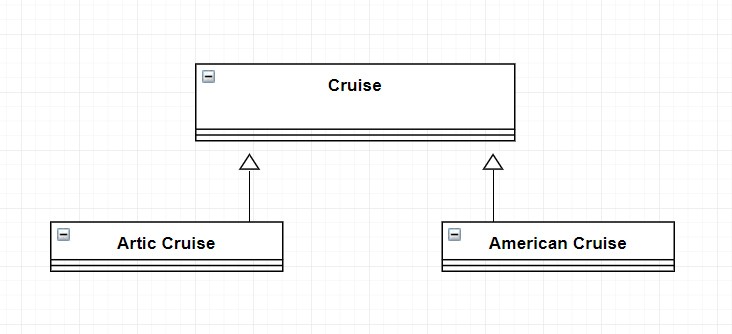
Our American and Artic cruises now can use the same attributes and operations of the Cruise class.
Columbus Travels is a brand new business and to gain market share from its competition the owned decided that they need to be able to discount some cruises and offer trips and an advantageous price.
As the web developer responsible to create the application, the first thought would be to create another attribute with the discounted price or a boolean that check whether the cruise is currently full-priced or not,
That is a sloppy solution, we can take advantage of Unified Modeling Language to find a better answer to this problem.
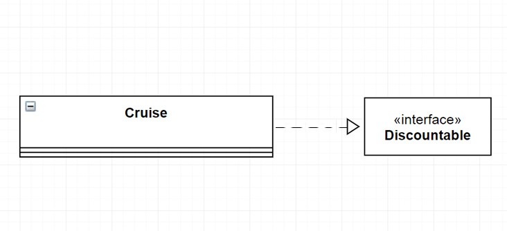
How about using an interface?
We can create a Discantauble interface like we saw above and implement it to our cruise class.
To do that class diagram uses a dashed line with the arrow pointing at the interface,
Like so:
Creating Associations between classes
Our application is starting to getting closer to its final shape, we are using UML to create reliable code and avoid doggy solutions that would add problems in the long run.
Something is still missing though.
We do not have any ships and for a cruise line company that may be a little problem,
let’s implement them in our software.
There are a lot of places to cruise to, only considering the Americans’ trip customers can select West coast, Carribean islands, Gulf of Alaska, New England, and South America oceans.
Which means a lot of ships!
It is time to talk about associations,
Using the class diagram you can describe the association among classes,
There are different types of association symbols but they all are represented by a solid line with one of two open arrows at the end (the direction and the number of arrows depending on the type of association).
Another way to describe association is by typing the type of relationship among the elements
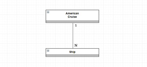
In our case, there can be one or more ships for each type of cruise
This is how we represent it.
Aggregation and Composition
Aggregation and Composition resemble associations, they explain a circumstance in which a class holds a reference to one or more instances of another class.
The symbol of aggregation is a line that starts with an unfilled diamond.
Columbus Travels’s application has now its cruises, it can discount the price if they need and each cruise has several ships available.
And right now, they are all there in the shipyards,
still waiting for someone to turn the engine on.
We just realized that the cruise staff is missing in our application.
What kind of relationship there is between the staff and the business?
Well, it is true that each member of the staff “belongs” to a determined ship, it is also true that if a ship is temporarily in maintenance or will not be available for a while, the member will still be in the payroll.
Most probably the member will just be moved to another ship.
That is called aggregations and it a soft relationship between classes.
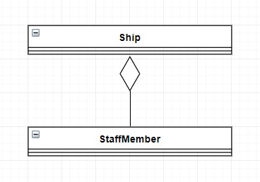
Now let’s see another type of relationship, a much stronger one.
“There is only one boss. The customer―and he can fire everybody in the company from the chairman on down, simply by spending his money somewhere else.”
Sam Walton, founder of Walmart.
Here is what we are missing the customers, how to we add customers to our applications?
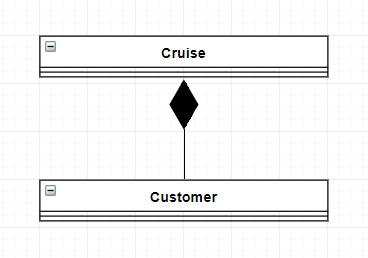
Unlike the relationship between ships and personnel, this is a much stronger relationship, with no customers there won’t be any cruises.
In a UML diagram, this is what is called composition.
In composition, a cruise should be deleted every time there are no customers.
The way to represent composition is the same as aggregation, only this time the diamond is filled
The usage relationship
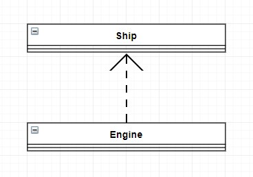
The usage relationship also called use or dependency is used when a class requires other class to be implemented,
The class is dependent upon the other element, that is called the supplier.
In our case study, for instance, we can add a class engine and say that our ships require to have a functional one to be able to travel around the world.
Adding notes to our UML diagram
Sometimes this type of diagram can be difficult to analyze.
Either the structure is not clear or look like there isn't a sense in the relationships.
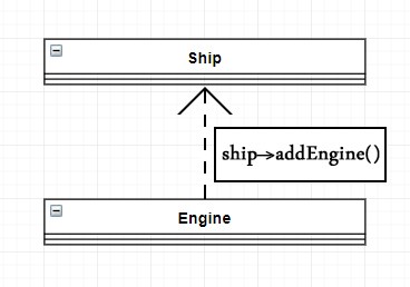
To solve this problem you can use notes,
Notes are very helpful in case you need to describe a process or a mechanic in the UML.
They are drawn as a box and often contains pseudocode.
The sequence diagram
UML can be described as a set of different diagrams, so far, in this tutorial, we have just seen the class diagram, it describes the classes and relationship we have in our system.
Another diagram often used by web developers is the sequence diagram.
A sequence diagram is a type of UML diagram that shows how an object in a system or classes within code interact with each other.
They are very useful because they show the interaction in the order they take place, as a flow of events.
Let’s continue with our application for Columbus travels,
We are going to create a rough sketch of a sequence diagram that includes the steps from a cruise creation until we allow the customer to buy the ticket.
In this diagram, we are going to have the customer which is the one that act, for this reason, it is called actor, and as other elements we have objects, and they are the cruise itself, the ship that will do the trip and the member of the staff.
The sequence diagram describes the right sequence that a project has to follow, and it is doing so by illustrating the steps one by one and the methods that each class performs.
The goal here is to make a customer able to buy a cruise ticket,
First thing first, let’s imagine that we need to instantiate an object from the Cruise class, then we add a ship to this cruise passing or injecting an instance of a ship, we do so with the method addShip(), next step would be to embark some staff to work on that ship, same concept we can do that calling the method hireStaff() from the class Ship and pass the staff object we want to hire, now that we have a ship and its staff ready it is time to decide the destination, this method can return an object, instance of class Destination, a string or even an array, with all the destinations in sequential order, that is not important in this moment of the project.
Eventually, we want the customer, an instance of the Customer class to be able to buy a ticket, we will need the buyTicket() method that refers to the cruise he/she wants to buy.
The boxes below show the lifespan the represent the focus of a process, the diagram is working from the top to the bottom, in here you can see how the process move among the different objects in the system.
As an additional detail, you can prefix the methods name with square parenthesis to describe a condition
Or you can use *[] to describe a loop that will be performed foreach instance of the class it is on.
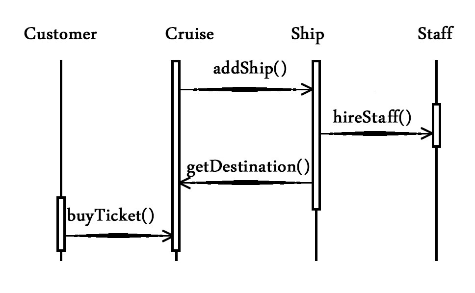
This diagram is very useful to have an idea of how the system needs to work also notice how these two models show polymorphism, how transparent these details became when we show the communication among objects.
Conclusion
Cristoforo Colombo was an incredibly talented explorer, his vision changed the world forever.
Don’t be fooled by his story though, he needed 3 of the best-designed ships available within the whole Spanish empire, some of the best crew members of its time and several years of preparations,
He was lucky in discovery America but if not, he designed systems that would lead him to arrive at the Indies.
We can also create designs that are so performant for our application by leveraging standards like UML.
***
Now that you know how to best design your next application it is time to dive into the code, you can do so and use the best practice by start reading this series about the best practice to write in PHP

